How a Bridge Rectifier works – Step by Step Tutorial
What is a Rectifier?
In the electronics industry, one of the most popular applications of semiconductor diodes is to convert alternating current (AC) signal of any frequency, which is typically 60 or 50 Hz, to a direct current (DC) signal. This DC signal can be used for powering electronic devices, rather than batteries. The circuit which converts the AC into DC signal commonly consists of a particular arrangement of interlocked diodes and is known as a rectifier. In power supply circuits, two types of rectifier circuits are commonly used — half-wave and full-wave. Half-wave rectifiers only permit one-half of the cycle through, whereas full-wave rectifiers permit both the top half and bottom half of the cycle through, while converting the bottom half to the same polarity as the top. This difference between them is shown in Figure 1.
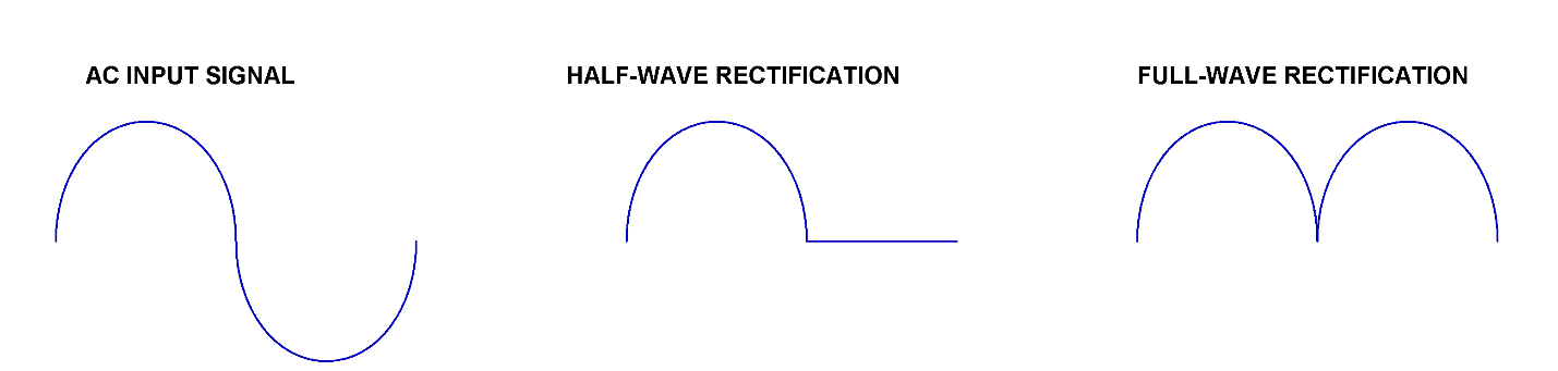
Figure 1 : Difference between outputs of half- and full- wave rectifiers
Between the two types, the full-wave rectifier is more efficient as it uses the full cycle of the incoming waveform. There are two types of full-wave rectifiers — the center-tapped full-wave rectifier, which requires a center-tapped transformer, and the bridge rectifier, which does not need a center-tapped transformer. The bridge rectifier will be discussed in this article as it is the most popular and usually comes in preassembled modules, making them easier to use.
How does a Bridge Rectifier work?
Bridge Rectifiers use four diodes that are arranged cleverly to convert the AC supply voltage to a DC supply voltage. The output signal of such a circuit is always of the same polarity regardless of the polarities of the input AC signal. Figure 2 depicts the circuit of a bridge rectifier with diodes interlocked in a bridge configuration. The AC signal is applied at the input terminals a and b, and the output is observed across the load resistor R1.
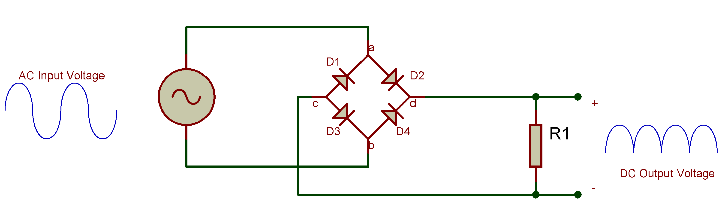
Figure 2 Bridge Rectifier with load resistor
Let’s see how this rectifier circuit responds to an AC signal with changing polarities at every cycle:
- In the first positive half cycle of the AC signal, the diodes D2 and D3 become forward biased and start conducting. At the same time, the diodes D1 and D4 will be reverse biased and will not conduct. The current will flow through the load resistor via the two forward-biased diodes. The voltage seen at the output will be positive at terminal d and negative at terminal c.
- Now, during the negative half cycle of the AC signal, the diodes D1 and D4 will be forward biased and diodes D2 and D3 will become reverse biased. The positive voltage will appear on the anode of D4, and negative voltage will be applied to the cathode of D1. It is worth noting at this point that the current that will be flowing through the load resistor will have the same direction as it has with the positive half cycle. Therefore, no matter the polarity of the input signal, the output polarity will always be the same. We can also say that the negative half cycle of the AC signal has been inverted and is appearing as a positive voltage at the output.
How does the capacitor work as a filter?
Nonetheless, this output voltage of single polarity is not pure DC voltage, as it is pulsating and not a straight line in nature. This problem is quickly solved by connecting a capacitor in parallel with the load resistor as shown in Figure 3. In this new design, the positive half cycle will charge the capacitor via the diodes D2 and D3. And, during the negative half cycle, the capacitor will stop charging and will begin to discharge itself through the load resistor.
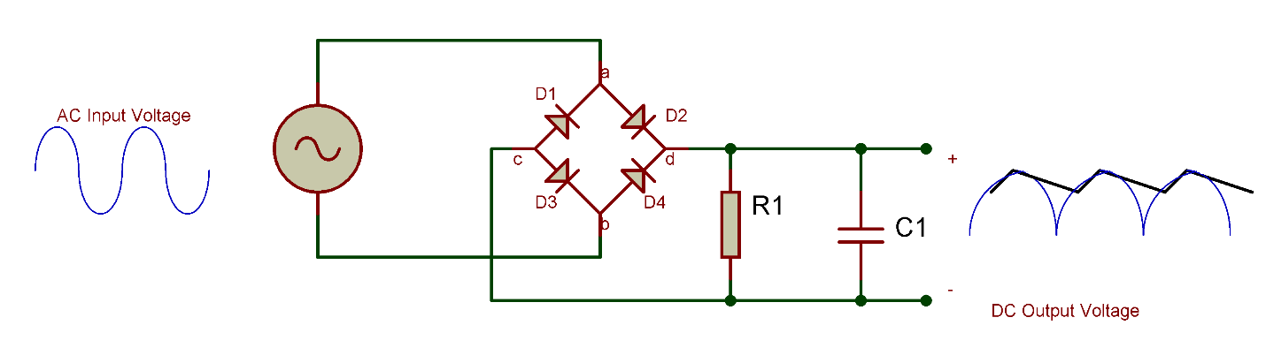
Figure 3 Bridge Rectifier with load resistor and filter capacitor
This process is known as filtration, and the capacitor acts as a filter. The capacitor has improved the pulsating nature of the output voltage, and it will now only have ripples. This waveform shape is now much closer to a pure DC voltage waveform. The waveform can be further improved by using other types of filters such as an L-C filter and pie filter.
Types of Bridge Rectifiers
The bridge rectifier just discussed is a single-phase type, however, it can also be extended to a three-phase rectifier. These two types can be further classified into full controlled, half controlled, or uncontrolled bridge rectifiers. The circuit that we just discussed is uncontrolled since we cannot control the biasing of the diode, but if all the four diodes are replaced with a thyristor, its biasing can be controlled by controlling its firing angle via its gate signal. It results in a fully controlled bridge rectifier. In a half controlled bridge rectifier, half of the circuit contains diodes, and the other half has thyristors.
Applications of a Bridge Rectifier
- For supplying polarized and steady DC voltage in welding.
- Inside power supplies
- Inside battery chargers
- Inside wind turbines
- To detect the amplitude of modulating signals
- For conversion of high AC to low DC voltage
Browse and Shop Bridge Rectifiers
Contact Us
Accepted Payments