The Zener Diode – What it is, how it works and it’s history
What is a diode & how does it work?
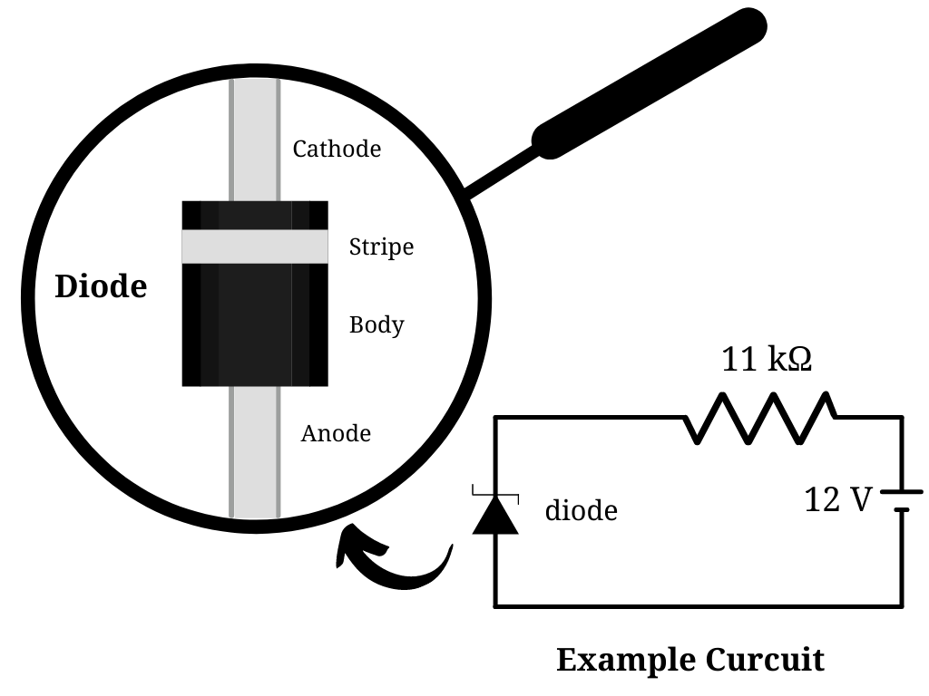
A diode is a circuit component that only enables current to flow in one direction. Diodes come in different sizes, and they typically have a black cylindrical body with two leads coming to the sides (Anode and Cathode) and a stripe at the Cathode end. Diodes are like one-way streets. The current can only move from the Cathode end to the Anode end through the diode. This occurs because the diode prevents current from flowing in the opposite direction from the Anode side. A diode is reverse biased when it acts as an insulator and forward biased when it allows current flow. A diode’s anode and cathode are its two terminals. Diodes are used in circuits to limit voltage and convert AC to DC. Semiconductors like silicon and germanium are employed to get the most out of diodes. Even though they both transfer power in the same direction, the way they do so is different. Diodes come in various shapes and sizes, each with its own set of applications, such as Zener diodes. Switches, signal modulators, signal mixers, rectifiers, signal limiters, voltage regulators, etc., are all examples of diode applications.
What makes a Zener diode different from a regular diode?
Zener diodes are one of the diodes used for particular purposes. Except for one key distinction, Zener diodes work just like conventional diodes. The reverse-breakdown voltage of Zener diodes is known as “Zener Voltage.” This means that Zener diodes can only stop current from flowing through a circuit up to a particular voltage. If the reverse-breakdown voltage of a Zener diode is 10 V and the current flow is only 5 V, the Zener diode will block the current flow. In another scenario, if the circuit’s current flow is 11 V, the Zener diode will allow the current to pass.
What is the point of a diode that conducts in both directions? you might wonder. A Zener diode comes in handy when creating voltage regulators, over-voltage protection circuits, and other circuits. It may be used to navigate partial current flow in a different direction in a circuit. The construction of Zener diodes also differs from the construction of regular diodes. These diodes are manufactured from severely doped N and P-type semiconductors, varying amounts of doping to achieve varying breakdown voltages. As a result, different voltage levels of Zener diodes have varied voltage capacities.
In summary, Zener diodes are designed to be used in reverse-bias mode, with a low, steady breakdown voltage, or Zener voltage. They begin to conduct significant reverse currents. A Zener diode can work as a voltage regulator by functioning as an auxiliary load, pulling more current from the source when the voltage is too high and less current when the voltage is too low.
The early history of the Zener diode
Clarence Melvin Zener was the one who initially described the benefits of this diode. Clarence Zener was a professor in the Department of Physics at Carnegie Mellon University. His research interests were in solid-state physics. He graduated from Stanford University in 1926 and obtained his doctorate from the same institution in 1929. In 1950, he invented the Zener Diode, which is now used in modern computer circuits. In 1934, Clarence Zener released a paper on the breakdown of an electrical insulator. He was known worldwide for pioneering a field of science called “internal friction,” which was the focus of most of his research.
How to protect your circuit from over-voltage damage with a Zener diode?
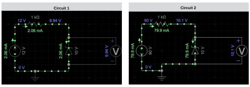
You may be experiencing unknown or mysterious failures in your projects when utilizing voltage-sensitive motors or other components in a circuit. Voltage-sensitive components can sometimes burn because simply they cannot handle the amount of voltage in the current. Let’s take a look at the circuit figures. Circuit 1 has a 12 Volt power supply with a reverse-biased Zener Diode. The Zener voltage is 10 Volt; therefore, the breakdown voltage has been exceeded by the 12 Volt power supply and doesn’t allow more than 10 Volts to the Voltmeter. If we increase the voltage of the power supply to 90 Volts as shown in the circuit 2 diagrams, then the Zener Diode will still allow the current to flow past it. However, the current that goes to the Voltmeter is still about 10 volts. Hence, the Zener diode can be used to create a voltage regulator using this logic in a circuit.
Attributes of Zener Diodes
Nominal voltage, power dissipation, forward drive current, forward voltage, packaging type, and maximum reverse current are attributes that are used to classify different Zener diodes. Let’s get to know some of these attributes.
Nominal Voltage
Zener Breakdown Voltage is also called the Nominal Operation Voltage. It is one of the important parameters for Zener Diode selection.
Power dissipation
The greatest amount of power that the Zener current can discharge is represented by this value. Exceeding this power rating causes the Zener diode to overheat, potentially damaging it and causing the failure of the components connected to it in a circuit. As a result, while choosing a diode for a specific application, this element should be considered.
Maximum Zener Current
At the Zener voltage, this is the maximum current that may be passed through the Zener diode without destroying it.
Minimum Zener Current
This is the minimum current required for the Zener diode to enter the breakdown area and begin working.
Other parameters that act as diode specifications must all be carefully studied before deciding on the type of Zener diode required for any particular design.
Shop Variable Resistors
Check out other articles from our Blog
A Brief History and Overview of Microelectronics
1. What is Microelectronics?
Microelectronics is a subfield of electronics that studies tiny complex machines or micro-chips that allow most of our devices to function, such as our cellphones. A microprocessor is a microchip. It is crucial in the field of microelectronics with billions of transistors per square centimeter, amplifying, controlling, and generating electrical signals. These transistors function as on and off switches that allow microelectronics to perform various Boolean operations by storing 1s and 0s. The Boolean operation or switching takes as little as 10 trillionths of a second. These transistors are tiny and unbelievably fast, allowing our modern devices to become smaller and faster in various applications.
2. History of Origin
Microelectronics has revolutionized the field of electronics and is rapidly transforming our lives and our world. The most fundamental building block of microelectronics, the transistor, was invented in 1947. John Bardeen Walter Brattain and William Shockley demonstrated the point-contact transistor to their co-workers at Bell Labs in New Jersey. The point-contact transistor is the first form of the transistor and was made from gold foil strips pressed into contact with a slab of Germanium on a plastic triangle. It is the size of a thumb which is much larger than the modern microscopic transistors.
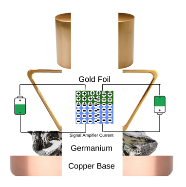
The First Transistor
Bardeen, Brattain, and Shockley connected a microphone to one end of the unit and a loudspeaker on the other to test the amplification. The men took turns picking up the microphone and whispering, “Hello.” “HELLO!” yelled the loudspeaker on the other end of the line. This moment is significant to microelectronics because it is followed by a technological revolution throughout the world. The progress in microelectronics has been focused on shrinking the circuitry embedded onto chips.
A decade later, Jack Kilby invented the integrated circuit (IC), a small circuit containing electronic components, including transistors, resistors, capacitors, and other components. Kilby worked for Texas Instruments, a semiconductor manufacturer, as an electrical engineer. Since each component had to be wired to any other component, he was irritated by the limited technical advancements. Because of the wires, the number of components used in devices was limited and sensitive to damage. Kilby constructed a circuit entirely out of semiconductors using Texas Instrument’s knowledge of silicon transistors and semiconductors. Kilby’s final product, the integrated circuit, eliminated the need to wire each part individually. It was much smaller than any other previously devised circuit.
In 1965 Gordon Moore, one of the co-founders of Intel, published his observation regarding the future of microelectronics in the Electronics Magazine. Moore stated that the computing power of integrated circuits would increase exponentially along with the advancement of transistors over time, while the cost would decrease exponentially. The size of transistors shrank dramatically, and the number of transistors used in circuits grew rapidly. Moore’s observation drew a lot of attention and became known in the scientific world as Moore’s law. Moore’s law continues to be an accurate prediction of microelectronics’ future.
Intel developed and introduced their first microprocessor, the 4004, chip in 1971. Intel designed the 4004 microprocessors with 2,300 transistors, which resulted in as much processing power as the room-filling ENIAC. Intel continually develops microprocessors with better processing powers that power most desktop computers to this day. The advancement of technology is at its peak, from phones to drones. Microelectronics plays a prominent role in humanity’s past and continuing progress in technology. Nanotechnology is expected to be the future of microelectronics, with far smaller components processing at much faster speeds.
3. The Invention and Design of Semiconductor Components
Semiconductor memories are information-storage microelectronic circuits. There are two types of memories: read/write and read-only memories (ROMs). Silicon and Germanium are metalloids, and their crystalline structure enables them to conduct electricity while still acting as insulators, thanks to their chemical elements. In addition, silicon is the most abundant element in the Earth’s crust. These materials and other passive components such as resistors, inductors, and capacitors are used to create microelectronic devices. A silicon chip will serve as the base to activate and deactivate the components in a controlled manner to send signals for a brief period. Despite its great usefulness, however, silicon cannot satisfy all demands of microelectronics. Microelectronics manufacturers are in search of a faster and more invincible material to integrate into circuits.
Making any microelectronic system entails several measures. In this regard, integrated circuits are the most complicated. Circuit design and chip fabrication are the two parts of the process. When creating an integrated circuit, a complicated staging method is used to transmit a signal to the desired output 3. This necessitates reading a textbook, but an application on how the chip functions can be addressed.
4. Application Example: RFID
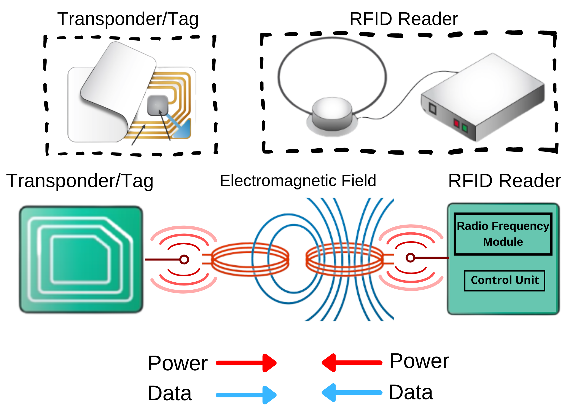
RFID stands for Radio Frequency Identification. It is a wireless technology that uses a chip electromagnetic frequency to identify something. RFID systems are used in most passports, vehicles, contactless card payments, smartphones, key fob, and more. An RFID system consists of a transponder (tag) and a reader.
RFID readers are made up of a radio frequency module, a control unit, and an antenna that generated an electromagnetic field. On the other hand, a tag consists of a single antenna for receiving and transmitting signals and an integrated circuit (IC) that stores and processes data while controlling and decoding radio-frequency (RF) signals from the antenna.
An interaction happens between a tag and a reader when they are close enough to share an electromagnetic field. This interaction ignites voltage in the tag’s antenna to power up the tag’s microchip. The microchip receives power and data of requests from the reader and returns the requested data to the reader.
Since World War II, RFID technology has been a longstanding technology used to identify approaching friendly aircraft and enemy aircraft by the British military. The manufacturing of RFID chips has expanded in the last two decades. RFID technology has also enabled state-of-the-art techniques and advances in microelectronics health monitoring through contactless testing. Their use spread very quickly among many industries, from healthcare to ware stores.
5. Career Goals to become an Electronic Design Engineer
To pursue a career as an Electronics Design Engineer, one must enroll in an ABET-accredited institution and pursue a bachelor’s degree in Electrical/Computer Engineering. Telecommunications engineering, signal processing, instrumentation, control engineering, and microelectronics are all subfields of an Electronic Design Engineer. An aspiring engineer must hone their expertise in product analysis, testing, and design to work in various industries. Working with project managers often requires coordination and time management in presenting, budgeting, completing tasks on time, and maintaining consistency. Nowadays, there are more specialized bachelor’s programs such as Microelectronic Engineering, where students can incorporate microelectronics or nanoelectronics circuits and sensors into a variety of products with a microelectronic engineering degree.
By: Arda Sengun & Richard Rojas
Printed Circuit Boards – Overview and Explanation
Printed Circuit Boards
- A printed circuit board is an electrical circuit used to mechanically support electronic components and to connect them electrically using conductive tracks. The term PCB is used as an abbreviation for the printed circuit board. It’s important to note the difference between a blank PCB and a PCB with components. A blank PCB is a plate without any soldered components, whereas a PCB with components has various resistors, capacitors, connectors, ICs, etc. mounted on its surface.
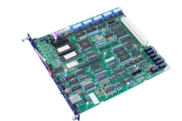
Figure 1: Printed Circuit Board with Components
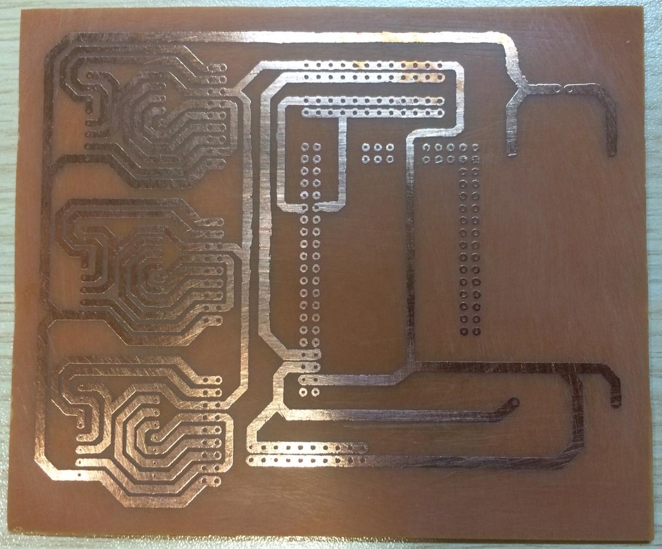
Figure 2: Blank Printed Circuit Board
- All the electronic components are either connected to the PCB or assembled by soldering. If the PCB had not been invented, all components would be connected by a large number of wires, which would reduce the reliability of circuits and increase the complexity of the design. Fortunately, printed circuit boards have been used for a long time, as they provide structure and organization for tons of electronic components to be mounted on their surface. PCBs can be easily customized for any application using computer-aided design (CAD) and manufacturing (CAM) software. This software helps electrical engineers design models of PCBs on the computer first before actually building the circuit itself.
- As you can tell, printed circuit boards (PCBs) are extremely common and are one of the essential blocks of modern electronic equipment.
Types of Printed Circuit Boards
- Nowadays, a modern computer printed circuit board looks like a multilayer labyrinth of hundreds of copper wires. Due to the mature printed circuit board manufacturing technology, PCBs have a variety of chemical and mechanical properties. So, it is really important to have an adequate understanding of how PCBs are made and what the main features are.
- Several types of printed circuit boards are available for circuit design. Printed circuit boards are traditionally classified according to their physical and chemical properties. PCBs are manufactured in one, two, or multi-layers depending on the complexity of the circuit. Although there are various types of printed circuit boards for customers, the most popular are the four main PCB types shown in Figure 3.
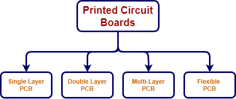
Figure 3: Printed Circuit Board
- Single Layer PCB is a low-cost printed circuit board that has only a single conductive layer above the substrate.
- Double Layer PCB has an FR4 substrate layer between two conductive layers. Since through-hole electronic components and surface mount (SMD) components can be soldered on both sides of this type of PCB, the solder mask is applied to both sides of the printed circuit board.
- Multi-layer PCB is a printed circuit board with more than two conductive layers. This type of printed circuit board should have a minimum of three conductive layers. All conductive layers are interconnected by copper-plated holes. This type of PCB is commonly used in computer motherboards.
- A flexible PCB is an easily bent printed circuit board. It saves considerable amounts of space compared to a regular rigid printed circuit board. Flexible PCBs can be produced as single, double, or multi-layer. They are often used in solar panels and smartwatches.
Construction of the Printed Circuit Board
- There are several different types of materials that are used to manufacture printed circuit boards. The materials, substrates, chemical properties, and construction are based on the type of circuit that’s being designed and its application.
- PCBs are categorized in terms of their heat resistance by the term called FR which means flame retardant. There are several types of flame-retardant (FR) printed circuit boards, however, the FR4 type is the most popular choice. FR4 is a composite material composed of woven fiberglass fabric with flame-resistant epoxy resin binders. FR4 is very popular due to its better stability with differences in temperature compared to other flame-retardant substrates. It is also easier to place FR4 between the conductive layers in the PCB.
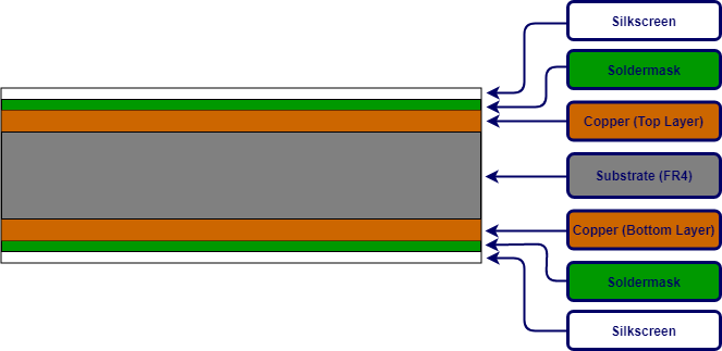
Figure 4: Construction of the Double Layer Printed Circuit Board
- Fıgure 4 is a diagram of how a double-layer PCB is constructed using an FR4 substrate. As you can see two conductive (copper) sheets cover the (non-conductive dielectric) substrate. All components are mounted on the (copper) upper and lower layers of the printed circuit board.
- There is another layer on the copper layer called the solder mask. This layer can be recognized commonly by its unique green color, but also it can be in any other color. A solder mask is used as an insulating layer to prevent unwanted contact of copper traces with other conductive materials on the PCB.
- The silkscreen is an additional layer on top of the solder mask layer that is used to print text, lines, or any shape on the surface of the printed circuit board. Epoxy ink is generally used for the screen printing process. The silkscreen layer can be used on the top and/or bottom layer of the printed circuit board according to user needs.
Variable Resistor – Overview and Explanation
An Overview on Variable Resistors – Construction, Working and Different Applications
What is a Resistor Overview
- In an electric circuit, the resistor is a passive, two terminal component that obstructs the flow of current and dissipates power once current flows through it. It is represented in electric circuits by the symbol in Figure 1. The ratio of voltage to current is called the resistance and expressed by Ohm’s Law as shown in Figure 2.
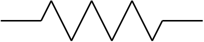
Figure 1: Resistor Symbol
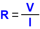
Figure 2: Ohm’s Law
- Ohm’s law states that current flowing through a resistor in an electric circuit is directly proportional to the applied voltage when the temperature remains constant. Therefore, it is logical to assume that normal resistors have two terminals and they have constant resistance since their resistance can not be changed.
Definition of a Variable Resistor
- As the name suggests, the variable resistor is a passive, three terminal device that can adjust its resistance via third terminal located between two terminals so that the obstruction to the flow of current goes up and down. Therefore, variable resistor circuit symbol has an arrow which represents resistance variation. The electrical symbol of variable resistor shown in Figure 3.

Figure 3: Variable Resistor Symbol
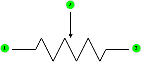
Figure 4: Variable Resistor Symbol
- The resistance of a variable resistor can be changed between zero to a certain maximum value with its third terminal. When the circuit diagram of the variable resistor in Figure 4 is carefully examined, you can see constant resistance exist between the terminals 1 and 3. Terminal 2 (in the middle) is the only terminal which has the ability to move. Therefore, in order to change resistance you must use anyone of the side terminals with the moving terminal.
Operation Principles of Variable Resistors
- Variable resistors are widely used in electric circuits to adjust the value of current or voltage, since the resistance of variable resistors can be set to a certain value. Variable resistors allow you to adjust the value of voltage by changing the resistance and keeping current constant . To adjust the input voltage, a voltage source is connected to the terminals 1 and 3 as shown in Figure 5. The output voltage between terminals 1 and 2 can be calculated by the voltage division formula shown in Figure 6.
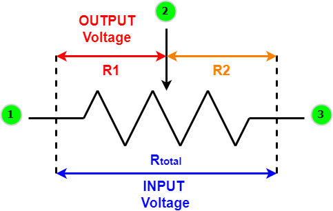
Figure 5: Usage of Variable Resistor as Voltage Divider
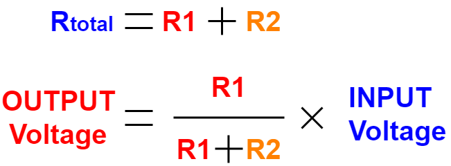
Figure 6: Voltage Division Formula
Construction of a Variable Resistor
- Although there are different types of variable resistors, their working principle is the same. When the inside of a variable resistor is examined such as Figure 7, there is a fixed resistance called the resistive track which is between terminals 1 and 3. Terminal 2 is connected to the knob and the slider (wiper) has a direct contact with the knob. The resistance between terminals 1 and 2 or 2 and 3 can be changed by adjusting the knob in the middle as represented by red circle in Figure 7.
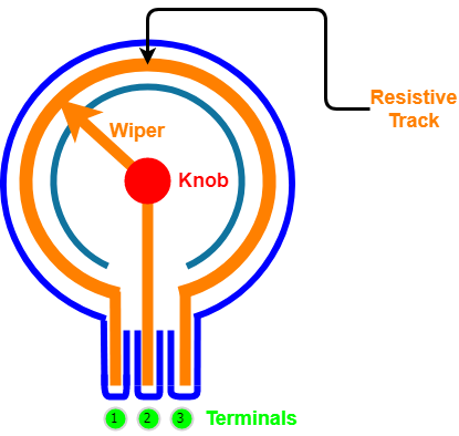
Figure 7: Variable Resistor
Types of Variable Resistors
- There are different types of variables resistors which all have almost the same working principle that was illustrated in the previous sections. However, terminal configuration and resistance value of a variable resistor can be adjusted with respect to various environmental parameters. These different types of variable resistors include:
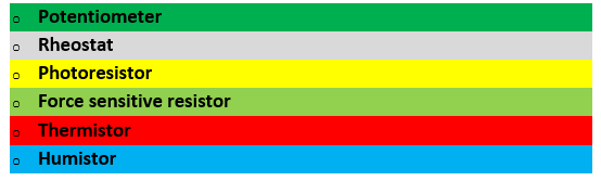
Potentiometers
- As mentioned in previous sections, variable resistors are often used to control voltage or current. Potentiometers is one of the most popular types of variable resistors. They are preferred in applications where voltage control is required. There are mainly two groups of potentiometers known as mechanical and digital. Mechanical potentiometers such as linear and rotary potentiometers have accuracy problems in vibrational circumstances. Digital potentiometers are commonly used due to sensitivity problem of mechanical potentiometers. One of the most fundamental uses of digital potentiometers is to come up with resistance drift problem that occurs in challenging environmental conditions. Since digital potentiometers can be adjusted by communication protocols such as I2C, they are also quite useful in cases where mechanical resistance adjustment isn’t possible.
Rheostats
- The construction of a rheostat is similar to that of a potentiometer. However, the rheostat’s moving terminal is short circuited with one of the side terminals as shown in Figure 8. Rheostats are preferred in applications where resistance adjustment or current limitation required.
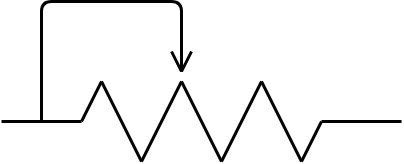
Figure 8: Rheostat Symbol
Photoresistors
- Photoresistors also known as light dependent resistors (LDRs) are a common type of variable resistor. Their resistance changes with respect to the intensity of incoming light due to the photoelectric effect. Photoresistors can be preferred in environments where intensity of the light varies.
Force Sensitive Resistor
- As the name suggests, the resistance of a force sensitive resistor changes with respect to the applied force level. They are generally used in robotic applications such as inside of the grippers of a robot.
Thermistors
- The resistance of a thermistor changes with respect to temperature. There are two types of thermistors known as negative temperature coefficient (NTC) and positive temperature coefficient (PTC) thermistors . The resistance of PTC thermistors is directly proportional to the temperature, whereas the resistance of NTC thermistors is inversely proportional to the temperature. Thermistors are preferred in different industrial applications where detection of the temperature variation is critical.
Humistors
- As the name suggests, the resistance of the humistor changes with respect to the variation of the humidity. Humistors are used in many internet of things (IOT) devices to detect environmental changes.
Applications of Variable Resistors
- Variable resistors are found in many of the devices/electronics we have in our homes. Some of these include radios, speakers, microphones, TVs, oscillators, smart home control devices etc. Potentiometers are generally used in home electronic appliances where speed or volume level control needed.
- Rheostats are used where current or resistance levels should be adjusted. A common example is the dimming of lights. In summary, variable resistors are popular in applications where voltage control or current adjustment required.
Shop Variable Resistors
Read more from our Blog
Tantalum Capacitors – Overview and Explanation
Tantalum Capacitors
Capacitor Overview
- In an electric circuit, the capacitor is a passive, two terminal device that can statically store electric energy between it’s terminals by using a technique called charge separation. The charge separation phenomenon occurs in capacitors due to the dielectric material placed between its metal plates. The capacitance (C) , the fundamental effect of capacitor, is measured in farads (F) which is named after the English scientist Michael Faraday. The capacitance of a capacitor is equal to one farad (F) when one coulomb (Q) of electric charge changes the electric potential between the plates by one volt (V). Capacitance is expressed by the equation in Figure 1.
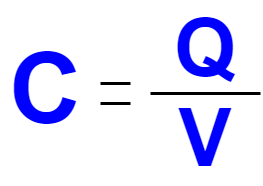
Figure 1: Capacitance Equation
- It is important to note that, there are also both fixed and variable capacitors similar to the case with resistors. Capacitors that have fixed values can be grouped into two categories with respect to their polarity as non-polarized and polarized capacitors. Electric symbols of the three most commonly used capacitor types are represented in Figure 2.
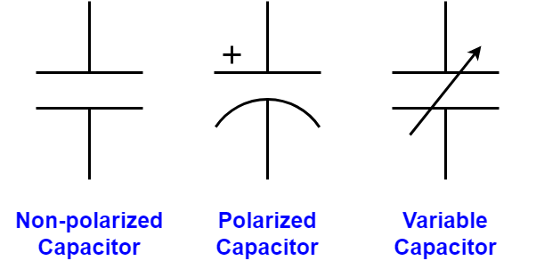
Figure 2: Capacitor Symbols
Definition of the Tantalum Capacitor
- As mentioned in the previous section, fixed and variable capacitors have different electric symbols and operation principles. Capacitors having fixed value of capacitance can be categorized into two groups as polarized and non-polarized capacitors. Polarized capacitors have asymmetrical construction and always must be operated with a higher voltage on the positive terminal (anode) than on the negative terminal (cathode). Polarized capacitors can also be grouped into two categories as electrolytic and super capacitors. An electrolytic capacitor’s positive (anode) plate is made of a special metal that forms an oxide layer. Then the oxide layer operates as the dielectric of the electrolytic capacitor through anodization. A liquid, gel or solid electrolyte covers the surface of oxide layer and behaves as the negative (cathode) plate of the electrolytic capacitor. The three families of electrolytic capacitors aluminum, tantalum and niobium are shown in Figure 3.
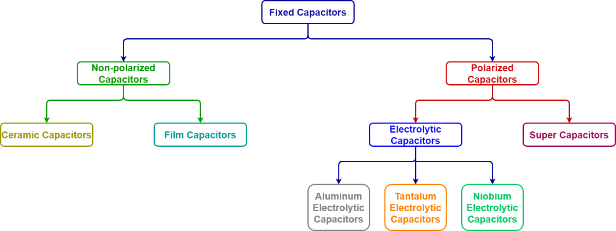
Figure 3: Types of Capacitors
- Without any doubt, the tantalum electrolytic capacitor is one of the most prevalent types of capacitors due to its much higher charge capacity than film or ceramic capacitors. Tantalum electrolytic capacitors have also less leakage and higher frequency response than aluminum electrolytic capacitors. Therefore, tantalum electrolytic capacitors are preferred in various electronic applications where small size and higher operation frequencies are needed. The niobium electrolytic capacitor is also an alternative to tantalum electrolytic capacitors and started to drawing more and more attention at the huge capacitor market due to its safety features such as higher flame retardation.
Construction of a Tantalum Capacitor
- Tantalum (Ta) is a bright, silver-gray metal element with the atomic number 73. When the cross-sectional view of the tantalum capacitor is examined such as a typical SMD tantalum electrolytic chip capacitor with solid electrolyte shown in Figure 4, it consists of tantalum powder pressed and sintered into a pallet as the positive (anode) terminal of the chip capacitor. The positive (anode) terminal is covered by an insulating oxide layer that forms the dielectric and the solid manganese dioxide electrolyte acts as the negative (cathode) terminal.
- Tantalum capacitors have high capacitance per volume and weight, because of their thin and relatively high permittivity dielectric layer which distinguishes itself from other electrolytic capacitors. Therefore, the large capacitance of tantalum electrolytic capacitors makes them suitable for passing or bypassing low-frequency signals, and storing large amounts of electric energy.
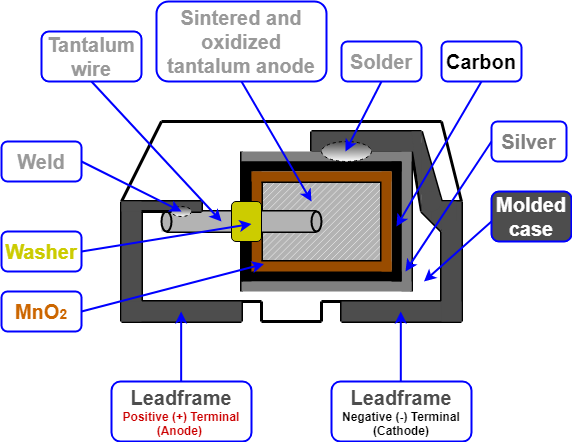
Figure 4: SMD tantalum electrolytic chip capacitor with solid electrolyte
Applications of Tantalum Capacitors
- Capacitors appear in all types of electronic devices from TVs, radios, computer equipment, Wi-Fi routers to mobile phones. Obviously, any piece of electronic equipment has several capacitors inside and those capacitors come in all shapes and sizes. Capacitors are produced using various methods of construction and dielectric materials that considerably affect their performances. Since some types of capacitors work better in some applications than others, understanding the differences between the different types of capacitors is extremely important.
- Tantalum capacitors are one of the most popular capacitor types in the microelectronics industry. More than 80% of all tantalum electrolytic capacitors are manufactured in surface mount device (SMD) style as tantalum electrolytic chip capacitors. However, niobium based electrolytic capacitors are also getting popular in electronics industry due to abundance of the niobium element in nature. Nowadays, the energy conservation requirements for capacitors is increasing due to the demand for low power applications. Since the equivalent series resistance (ESR) of a tantalum electrolytic capacitor is relatively low, they are still very popular in electronic application where energy saving is vital.
Shop Tantalum Capacitors
Read our other articles from our Blog
How Voltage Regulators Work – Step by Step Explanation
What is a Voltage Regulator
A voltage regulator is an electrical device whose sole purpose is to maintain a constant output voltage. It provides the desired output voltage regardless of any change in the input voltage or load conditions. Electronic circuits are dependent on voltage regulators since they require a stable voltage supply to avoid damage.
How does it work?
The voltage regulator uses the principle of a feedback control system. It relies upon negative feedback control loops.
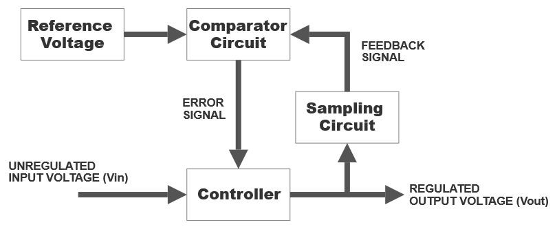
As you can see, a reference voltage signal is provided to the comparator circuit along with the feedback signal from the controller. The comparator circuit compares both values and sends the error signal to the controller. The controller regulates the output voltage using the error signal from the comparator.
Types of Voltage Regulators
Throughout the world, voltage regulators are the most common electrical component in any machine or device. There are two fundamental types of voltage regulators:
Linear Regulators
A linear voltage regulator works like a voltage divider. The resistance of the linear regulator varies with the connected load and input voltage. Therefore, it is able to supply a constant voltage signal.
Advantages and Disadvantages
Linear regulators have a lot of advantages, for example, they provide a low ripple voltage which means less fluctuation in the output voltage signal. It has a fast response time. Moreover, it has low electromagnetic interference and less noise.
The efficiency of the linear voltage regulator is low and it dissipates a lot of heat so a heat sink is needed. It also requires more space. One of the main disadvantages is that the output voltage cannot exceed the input voltage.
Types of Linear Voltage Regulators
- Shunt
- Series
Shunt Regulators
A shunt regulator is used for low-powered circuits. It works by directing the current away from the load and sending it into the ground. It provides a path from the input voltage to a variable resistor which is connected to the ground. It has a very low efficiency but since the wasted current has a very low value, it is neglected.
Applications
- Used to absorb current (Sink circuits)
- Amplifiers
- Voltage power supplies
- Electronic circuits that need a precise voltage reference
Series Regulators
The operation of a series voltage regulator is dependent upon the variable component which is connected with the load. When the resistance of the variable component is changed, the voltage drop across the component also changes. Using this technique, the voltage across the load remains the same.
One of the main advantages is that since the variable component and the load are connected in series, the current flowing through them is the same. Thus, the load effectively uses the current. Which makes it more efficient than a shunt regulator.
Switching Voltage Regulators
Switching voltage regulators consist of a series device that is repeatedly switched on and off at a high frequency. The duty cycle is used to control the amount of charge supplied to the load. The duty cycle is controlled by a feedback system that is very similar to the one in the linear regulator. Switching regulators have a high efficiency because the load is either on or off which means it dissipates no energy when it is off.
The switching regulator is superior to the linear regulator when it comes to the output voltage. Because it can supply an output voltage signal which can be greater than the input voltage. Furthermore, it can even generate an opposite polarity voltage signal.
Types of Switching Regulators
- Step Up (Boost)
- Step Down (Buck)
- Step Up/Step Down (Boost/Buck)
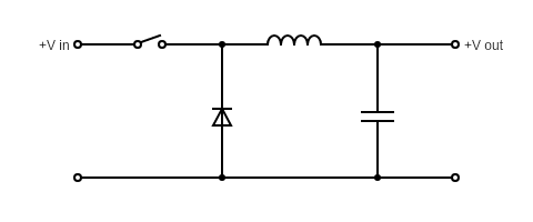
Step Up Regulators
Also known as a boost regulator, Step up regulators generate a higher output voltage signal by increasing the input voltage signal. This type of regulator is most commonly used to power multiple LEDs.
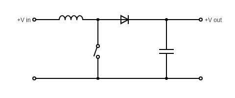
Step Down Regulators
Step Down regulators are also called buck regulators. They supply a lower regulated output voltage signal from a higher unregulated input voltage signal.
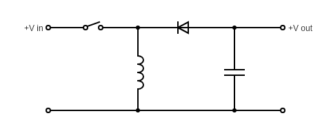
Step Up/Step Down Regulators
The purpose of this regulator is to increase, decrease or invert the voltage signal. Moreover, it is also called a voltage inverter circuit. Opposite polarity is achieved by the forward and reverse biasing action of the diode. During the off-time, the circuit charges the capacitor and when the capacitor is fully charged, it supplies the opposite polarity output. The efficiency of this type of voltage regulator is very high.
Transistor Voltage Regulators
Zener diodes have a mode due to which it can act as a voltage regulator. This mode is known as the reverse breakdown voltage operation. During this mode, the Zener diode maintains constant output DC voltage signal while the AC ripple voltage signal is completely blocked.

Applications of Voltage Regulators
There are many applications of voltage regulators. One of the most common examples is the mobile charger. The adapter is supplied with an AC signal. However, the output voltage signal is a regulated DC signal.
Every power supply in the world uses a voltage regulator to provide the desired output voltage. Computers, televisions, laptops and all sorts of devices are powered using this concept.
Small electronic circuits rely on regulators to operate. Even the slightest fluctuation in voltage signal can damage the components of a circuit such as ICs.
When it comes to power generation systems, voltage regulators play an essential part in its operation. A solar power plant generates electricity based on the intensity of sunlight. It needs a regulator to ensure a regulated constant output signal.
Shop Voltage Regulators
Learn and read more from our Blog
An Overview on Rheostats
Rheostat Overview – Construction and Working, Different Applications
Rheostats are resistors which are adjustable, and are used when applications require current adjustment or different resistance in an electrical circuit. Rheostats can adjust generator features, low lights, and start or stable the speed of electrical motors.
There are two things that affect the amount of current flowing into an electric circuit: the magnitude of the applied voltage and the overall resistance of that circuit. If the circuit resistance is lowered, the electric current flow that is passing through the circuit increases. Conversely, the electric current is limited if the circuit resistance is increased.
There is direct relation between the length of the wire to the resistance of the circuit. Increasing the length of the wire increases the resistance between in the circuit. Rheostats allows resistance to be changed, which in turn, either increases or decreases the current through the circuit. The need to add different resistors for varying resistances automatically disappears since a single rheostat can incorporate different resistances necessary for the circuit depending upon its range.
Construction and Working
A rheostat is a wire wound variable resistor which has two connection points: one is a moving point and the other one is a fixed point. Similar to a potentiometer, some rheostats can have three connection points (A, B, and C) as shown in Figure 1, but still, only two of them are used. In such cases, there are two fixed points (A and C), only one of which is used, and the second connection point is the moving one (B).
Rheostats also have to bear large currents when compared with potentiometers. Therefore, rheostats are made up of wire wound resistors. They are mainly constructed by wrapping the Nichrome wire across a ceramic core. Such a core behaves as an insulator to the heat energy and does not permit it to flow through the rheostat.

Figure 1 Rheostat internal Structure (Linear)
Figure 1 explains the working principles of a rheostat. As mentioned above, rheostats work on the principle that the resistance of a certain track or wire depends upon its length. Let’s assume that we are using the fixed connection point A and the moving connection point B of the rheostat illustrated in Figure 1. The rheostat will offer minimum resistance to the circuit if the slider lies closer to point A, since the resistive coil length is at a minimum. Therefore, a large current can flow through the circuit in this case.
Similarly, the rheostat will offer maximum resistance if the slider lies closer to point C, as the resistive coil length is at its maximum. Hence, a tiny amount of current would flow through the circuit and a large part of the current would be opposed by the rheostat.
Now, let’s say that we are using the fixed connection point C and the moving connection point B. In this case, when the slider is made to lie near point C, the rheostat would offer minimum resistance and maximum current flow through the circuit. Likewise, when the slider is moved near to point A, the rheostat would offer maximum resistance and minimum current flow through the circuit.
Finally, it is important to know the maximum and minimum resistances necessary for your circuit. Rheostats have maximum and minimum resistance ratings, and thus, they cannot offer resistance outside their inherited range.
Now you may be wondering if there is a high point up to which the resistance may be decreased or elevated inside the rheostat. For all rheostats, they come with a resistance rating, for instance if 50kω is the rating of the rheostat, the minimum resistance it will deliver is zero and the maximum will be near 50kω.
Different Applications
Rheostats are used in situations where high voltage is needed to transmit electricity. They either work as a variable resistor or as a potential divider. An example of rheostats working as a variable resistor is in dimmers. Fan dimmers and light dimmers frequently use rheostats to control the variation of speed and the intensity of light respectively.
Rheostats are used to change the intensity of light when the lights are dim. The flow of electric current decreases through the bulb. If rheostats resistance is increased the light brightness is lessened. Similarly, The flow of electric current increases through the bulb. If rheostats resistance is increased, the light brightness is increased.
When the rheostat amplifies its resistance, the electric current through the bulb is reduced and the light dims. This same process would slow a ceiling or portable wall fan. Radios are equipped with rheostats to manage volume. Motor speeds can also be controlled through rheostats. They can also be used to control temperature in an oven, a heater or an apartment.
Rheostats also work as potential dividers. Wheatstone bridge applies the same potential dividing principle. Different types of resistive sensors use the potential dividing technique, strain gauges, light dependent resistors and thermistors. Rheostats can be used to measure the resistance of a sensor through a microcontroller. Rheostats can accomplish high voltage readings as well as accurate logic level shifting.
Rheostats are still a primary and common component to control the discharging of current in an electrical circuit. However, solid state devices like triacs and silicon-controlled rectifiers (SCR) have taken the place of rheostats. Rheostats are less efficient than a triac and are less reliable because of presence of mechanical components.
They are mostly when circuits need to be tuned or calibrated. High voltage power lines also use rheostats as potential dividers. Low current and high voltage induce minimal losses in power transmission. This helps supply electricity to millions of homes around the globe.
An Overview on Proximity Sensors
Proximity Sensors – Different types, Functionalities, Applications and Market trends
There are many different types of sensors available today in the electronics market. Our focus in this discussion is a type of sensor technology called a proximity sensor. We will explain how proximity sensors work, the various types, and what these sensors are used for. We will also cover the increasing relevance of this technology as we move forward into the future.
What are proximity sensors?
Proximity sensors detect how far away a target (object being measured) is without physical contact.
How do proximity sensors work?
Depending on the type of proximity sensor, it will either emit an electromagnetic field, infrared radiation, sound or light beam. Once the beam/field is emitted from the sensor, it looks for any differences and changes in the return signal and then can determine the distance of the target.
What are proximity sensors used for?
They can be found in many different applications including, but not limited to, autonomous cars, smart phones, aircrafts, smart factories, etc.
What are the different types of proximity sensors?
There are many different types including inductive proximity sensors, magnetic proximity sensors, capacitive proximity sensors, photoelectric proximity sensors, and ultrasonic proximity sensors.
Inductive Proximity Sensors
This type of sensor is best used for detecting metal. The sensor can detect the distance of any metal object within the magnetic field.
Inductive proximity sensors are frequently built into metal fixtures. To prevent the sensor from detecting that metal fixture these applications require a shielded inductive proximity sensor.
Shielded inductive sensors increase the accuracy of the sensor but compromise on range. Unshielded inductive sensors have longer range but can not be mounted on or in certain metals.
Inductive proximity sensors are commonly used in industrial and military applications. One use case for the military is landmine detection.

Figure 1 : Inductive Proximity Sensor Diagram
Magnetic Proximity Sensors
This type of sensor can detect a variety of materials including metals, plastics and wood. These sensors includes a reed switch that detects nearby magnets. The reed switch makes contact when it nears a magnet and alerts the sensor.
These sensors are commonly used in large data/server centers and also in clean energy applications such as wind turbines and solar panels.
Capacitive Proximity Sensors
This type of sensor is able to detect metals and non-metals. Capacitive proximity sensors use two conduction plates that work like an open capacitor with air in between them. When something enters the sensors field, capacitance occurs and the system is alerted.
Capacitive proximity sensors are commonly used in industrial applications, specifically in automated production lines where they help in operating machine systems and positioning moving parts.

Figure 2: Capacitive Proximity Sensor
Photoelectric Proximity Sensors
This sensor works very well in areas where there are a lot of airborne contaminants. They work by emitting visible/invisible light to a receiver. If the beam of light is blocked, and the receiver detects a disruption or total blockage in the light beam, the system is alerted. Systems can either be alerted when light is received or when it is not received, depending on whether the sensor is a dark-on or light-on sensor.
These sensors are commonly used for automated doors, detecting colors, materials/ logistic applications, and for counting small objects.
Ultrasonic Proximity Sensors
This type of sensor emits sound waves from a transducer at very high frequencies. The sensor waits for the sounds to be reflected back and based on the time period, the sensor can accurately determine the distance of the target.
This type of sensor is used in self parking technology, anti-collision systems, manufacturing, and obstacle detection.
Proximity Sensor Market
The proximity sensor market in 2019 was valued at $2.94 billion and is projected to reach $4.45 billion by 2025, growing at a rate of 7% year over year.
Much of this growth is a result of increasing investment in automation hardware. This includes the likes of healthcare, industrial, automotive and smartphone markets.
Automotive markets are predicted to carry the largest amount of market share. We see a few different applications of proximity sensors in these markets.
For a touch-free user experience auto companies are equipping their vehicles with proximity sensors that allow keyless entry, 3D passenger modeling and interior lighting control. Proximity sensors are also being used in vehicles for parking assistance, anti-collision and fully autonomous driving systems.
Lastly, we also expect to see a significant increase of proximity sensors in the smartphone market. Many smartphones already have proximity sensors. Their main purpose is to conserve battery life by turning the display screen on or off based on your distance to the phone. For instance, you may notice how your smartphone turns its display off when the phone is placed up to your ear, or turns its display on when you’re looking at the screen.
In fact, Apple has created technology with proximity sensors that detects when your phone is falling, and prepares itself for an impact.
Clearly the applications for proximity sensors are seemingly endless. These are just a few examples of how they are being used today. As innovative technologies and products continue to be developed, we can expect exponential market growth.
Browse and Shop Sensors
Find more articles like this on our Blog
How a Bridge Rectifier works – Step by Step Tutorial
What is a Rectifier?
In the electronics industry, one of the most popular applications of semiconductor diodes is to convert alternating current (AC) signal of any frequency, which is typically 60 or 50 Hz, to a direct current (DC) signal. This DC signal can be used for powering electronic devices, rather than batteries. The circuit which converts the AC into DC signal commonly consists of a particular arrangement of interlocked diodes and is known as a rectifier. In power supply circuits, two types of rectifier circuits are commonly used — half-wave and full-wave. Half-wave rectifiers only permit one-half of the cycle through, whereas full-wave rectifiers permit both the top half and bottom half of the cycle through, while converting the bottom half to the same polarity as the top. This difference between them is shown in Figure 1.
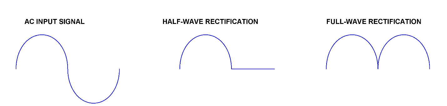
Figure 1 : Difference between outputs of half- and full- wave rectifiers
Between the two types, the full-wave rectifier is more efficient as it uses the full cycle of the incoming waveform. There are two types of full-wave rectifiers — the center-tapped full-wave rectifier, which requires a center-tapped transformer, and the bridge rectifier, which does not need a center-tapped transformer. The bridge rectifier will be discussed in this article as it is the most popular and usually comes in preassembled modules, making them easier to use.
How does a Bridge Rectifier work?
Bridge Rectifiers use four diodes that are arranged cleverly to convert the AC supply voltage to a DC supply voltage. The output signal of such a circuit is always of the same polarity regardless of the polarities of the input AC signal. Figure 2 depicts the circuit of a bridge rectifier with diodes interlocked in a bridge configuration. The AC signal is applied at the input terminals a and b, and the output is observed across the load resistor R1.
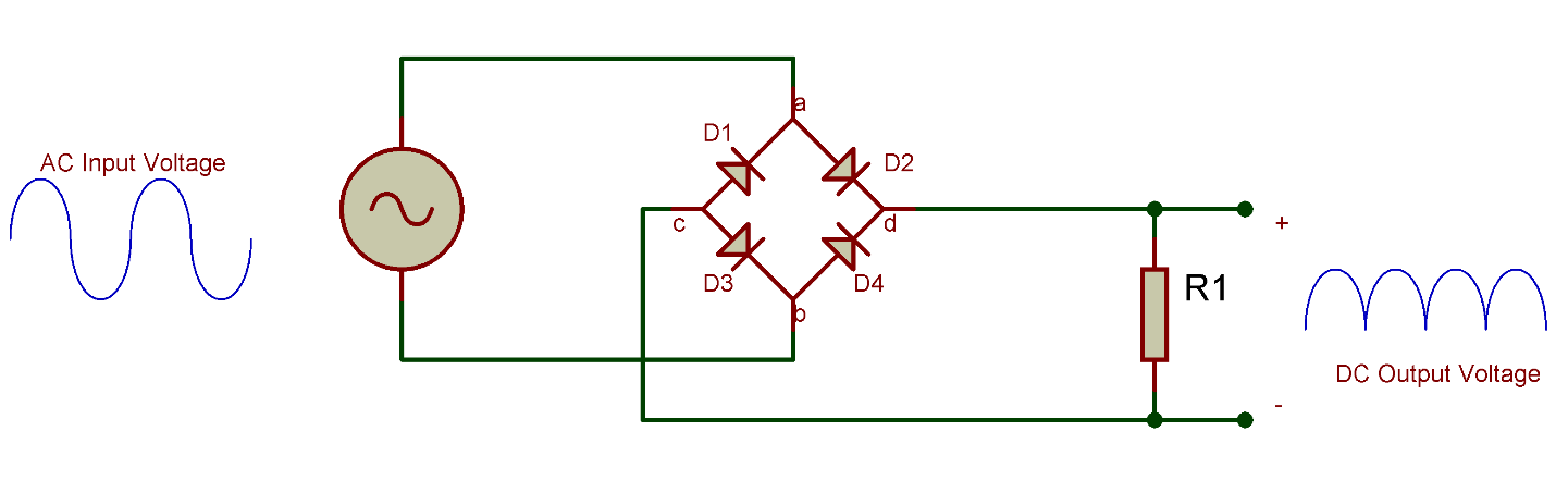
Figure 2 Bridge Rectifier with load resistor
Let’s see how this rectifier circuit responds to an AC signal with changing polarities at every cycle:
- In the first positive half cycle of the AC signal, the diodes D2 and D3 become forward biased and start conducting. At the same time, the diodes D1 and D4 will be reverse biased and will not conduct. The current will flow through the load resistor via the two forward-biased diodes. The voltage seen at the output will be positive at terminal d and negative at terminal c.
- Now, during the negative half cycle of the AC signal, the diodes D1 and D4 will be forward biased and diodes D2 and D3 will become reverse biased. The positive voltage will appear on the anode of D4, and negative voltage will be applied to the cathode of D1. It is worth noting at this point that the current that will be flowing through the load resistor will have the same direction as it has with the positive half cycle. Therefore, no matter the polarity of the input signal, the output polarity will always be the same. We can also say that the negative half cycle of the AC signal has been inverted and is appearing as a positive voltage at the output.
How does the capacitor work as a filter?
Nonetheless, this output voltage of single polarity is not pure DC voltage, as it is pulsating and not a straight line in nature. This problem is quickly solved by connecting a capacitor in parallel with the load resistor as shown in Figure 3. In this new design, the positive half cycle will charge the capacitor via the diodes D2 and D3. And, during the negative half cycle, the capacitor will stop charging and will begin to discharge itself through the load resistor.
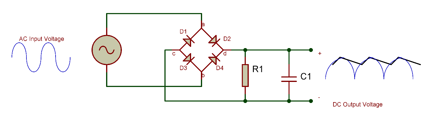
Figure 3 Bridge Rectifier with load resistor and filter capacitor
This process is known as filtration, and the capacitor acts as a filter. The capacitor has improved the pulsating nature of the output voltage, and it will now only have ripples. This waveform shape is now much closer to a pure DC voltage waveform. The waveform can be further improved by using other types of filters such as an L-C filter and pie filter.
Types of Bridge Rectifiers
The bridge rectifier just discussed is a single-phase type, however, it can also be extended to a three-phase rectifier. These two types can be further classified into full controlled, half controlled, or uncontrolled bridge rectifiers. The circuit that we just discussed is uncontrolled since we cannot control the biasing of the diode, but if all the four diodes are replaced with a thyristor, its biasing can be controlled by controlling its firing angle via its gate signal. It results in a fully controlled bridge rectifier. In a half controlled bridge rectifier, half of the circuit contains diodes, and the other half has thyristors.
Applications of a Bridge Rectifier
- For supplying polarized and steady DC voltage in welding.
- Inside power supplies
- Inside battery chargers
- Inside wind turbines
- To detect the amplitude of modulating signals
- For conversion of high AC to low DC voltage
Browse and Shop Bridge Rectifiers
Contact Us
Accepted Payments